Layout Tab

- Horizontal/vertical
measurement
- Absolute width – The absolute width of the horizontal and/or vertical measurement is entered to that of the diagram here. The pure length of abscissa and/or ordinates without text are to be considered.
- Scale to – Unlike the absolute indication, the application can take place scaled to an axis in the diagram. The absolute height results thereby subject to the minimum and maximum value on the axis.
- Factor – Information such as how many [mm] should assigned to a corresponding difference of size on the axis is required for scaled application. sisHYD calculates from it the necessary scale factor.
- Legend position
- Origin – Specifies the point of reference for the x-position and y-position values. The possible points of reference are the 4 corner points of the internal diagram surface – below left is the intersection of abscissa and ordinate.
- x-position – Specifies the horizontal offset of the legend relative to the origin. Negative values move the legend to the left.
- y-position – Specifies the vertical offset of the legend relative to the origin. Negative information moves the legend upwards.
- Draw legend – Specifies whether the legend is drawn or ignored.
- mm grid network
- Create grid network – Specifies whether a grid network is drawn into the diagram. The grid network always refers to the axes displayed under "scale to".
- Synchronize length
coordinate – The calculated path distances in flow, return (and KLB leaders)
may differ. In this case, identical node positions are drawn in in the network
at different positions on the length axis in the profile plot.
- When this option is
selected, sisHYD synchronizes the positions with one another.
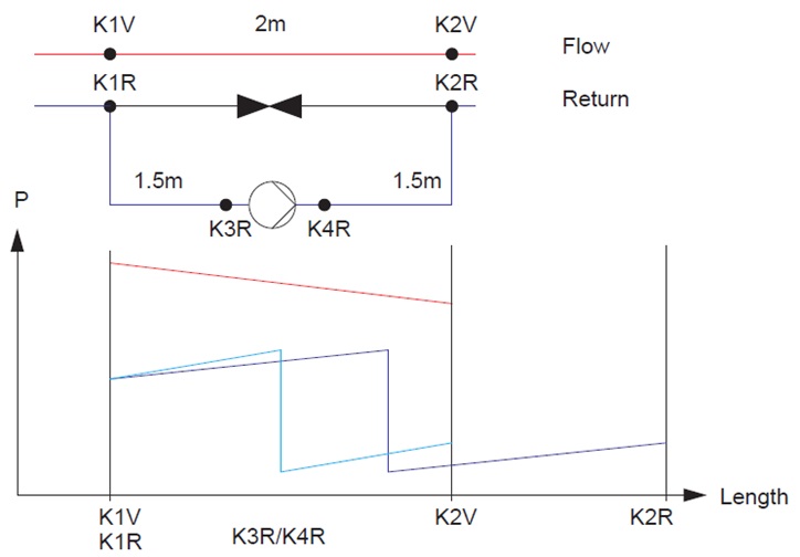
Note: For multi-leader systems of long-distance heating, paths in flow, return (and KLB leaders) are calculated. The selection of the path selection takes place however for exactly one of the possible leaders. sisHYD calculates the parallel paths in the further leaders. During this path calculation the actual pipe lengths are summed. Thus a different length coordinate can result for the node K1 in flow than for the node K1 in return.
- A further reason for different lengths are asymmetries in the network – e.g. installation of an pressure increase station in the return. sisHYD tries to bridge the unbalance by limited search with an alternative route. In this case the probability of different route distances is very high.
- When this option is
selected, sisHYD synchronizes the positions with one another.
-
- In the constellation illustrated a distance of 2m is calculated for flow (red) and a length of 3m for the return (blue). The synchronization works in such a way that it is balanced linearly within the section (turquoise). Therefore, for the node K3 the result is:
- Search depth for bypasses – The search depth for the calculation of alternative routes is limited in order to receive only meaningful bypasses. The numerical value entered here specifies how like many corners the search may result in.